Nomenclature
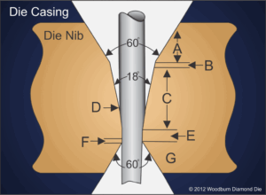
LEGEND
A. Approach Angle / Front Bell
B. Blend
C. Reduction Angle/Drawing Angle
(Shown at 18°. Normal for Soft Materials is 16° – 20°. Hard Materials is 12° – 16°.)
D. Wire Contact Area/Impact Point
E. Bearing Length (Shown at 50% of Hole Diameter. Normal for Soft Material is 20% – 40%. Hard Material is 40% – 60%.)
F. Polished Back Relief
G. Exit/Back Bell
Approach Angle – Also known as the Front Bell. The Approach Angle area accommodates both wire and lubricant. The approach area is designed so that, in the wet draw process, a consistent film of lubricant encases the wire as it travels along the die wall through both the reduction and bearing area.
Reduction Angle/Drawing Angle – The wire begins the deformation process in this area of the die. The Reduction or Drawing Angle is expressed in degrees.
Impact Point – This is the point of surface that first comes in contact with the drawn material. Normal wear patterns develop just below this contact point.
Bearing – The Bearing area creates the final exit size of the wire. The Bearing area length is expressed as a percentage of the hole diameter.
Polished Back Relief – This is a highly polished relief angle that helps to reduce metallic fines and potential wire shaving due to misalignment.
Exit – Also known as the Back Bell. The drawn material exits through this area of the die. Its shape provides the strength and support needed to withstand the drawing stresses.
[table id=9]


